14. Induction Motors and Two Phase Servo Motors (B)#
Objective
The purpose of this experiment is to demonstrate the operating principles of induction and servo motors. The basic parameters of a 2-phase servo motor will be measured and used to predict its torque-versus-speed characteristics for balanced operating conditions. The steady-state characteristics will be measured and compared with analytical predictions. Servo operation will be illustrated by varying the amplitude of one of the phase voltages.
14.1. Introduction#
The steady-state equivalent circuit of a 2-phase induction motor is shown in Fig. 14.1 below.
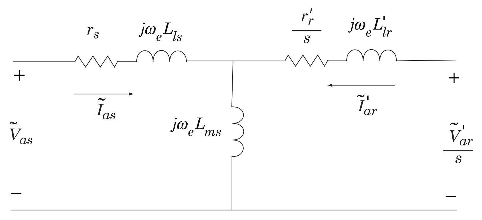
Fig. 14.1 Induction motor steady-state equivalent circuit.#
where
and
The electromagnetic torque can be expressed
With constant-amplitude constant-frequency balanced voltages applied to the stator windings
In (14.4), all \(X\)’s represent \(L\)’s multiplied by the source frequency, \(X = \omega_e L\). Also,
14.2. Prelab#
Read the preceding Introduction, and read or review Section 8.8 of EE 32100 text.
14.3. In the Laboratory#
14.3.1. Torque-Versus-Speed Characteristics#
Our first objective will be to measure the steady-state torque-versus-speed characteristics.
Connect the analog output of the torque transducer to Analog Input Channel 1. Set the gain switch to \(1\).
Connect the tachometer output to Analog Input Channel 2. Set the gain switch to \(10\).
Connect Analog Output Channel 1 to phase \(a\) of the induction motor (red to red), Analog Output Channel 2 to phase \(b\) of the induction motor (blue to red), and the induction motor return lead to the ground of either Analog Output Channel 1 or Analog Output Channel 2 (white to black).
Connect Analog Output Channel 3 to the armature of the DC motor (red to red, black to black).
Use the Simulink model,
slip_torque_target.slx(Fig. 14.2) , to provide a \(10\)-\(\V\) balanced 2-phase set of voltages to the stator windings connected to the power amplifier outputs, Channels 1 and 2, with a frequency of \(\qty{10}{\hertz}\). In addition, this model will provide a DC output to Channel 3. Initially set the DC voltage to \(0\). Set the To_IP_Address to the IP address of the host computer.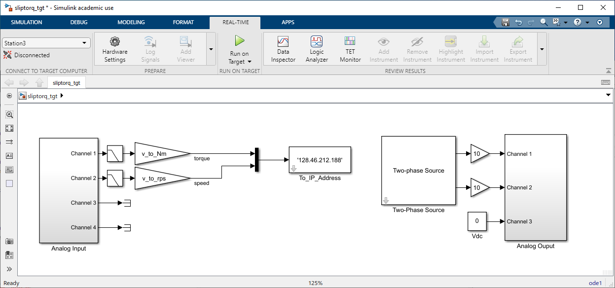
Fig. 14.2 Simulink target model for lab 14.#
With the Simulink model
slip_torque_target.slxrunning on the target computer, open and start the Simulink modelslip_torque_host.slx. Set the FromAddress to the IP address of the target computer. The host model will display the torque and speed of the induction motor. Vary the voltage applied to the DC motor so that the rotor speed varies over a broad range, roughly \(-60\) to \(60\) \(\radian\per\second\). This corresponds to an armature voltage of \(-4.5\) to \(\qty{6.5}{\V}\), respectively. At each value of DC voltage, allow the motor to settle to its steady-state torque and speed, and then toggle the switch from \(1\) to \(0\) to record a data point. After recording \(10\) data points, stop the host simulation, and save your MATLAB workspace by typingsave lab_14_ts.save lab_14_ts
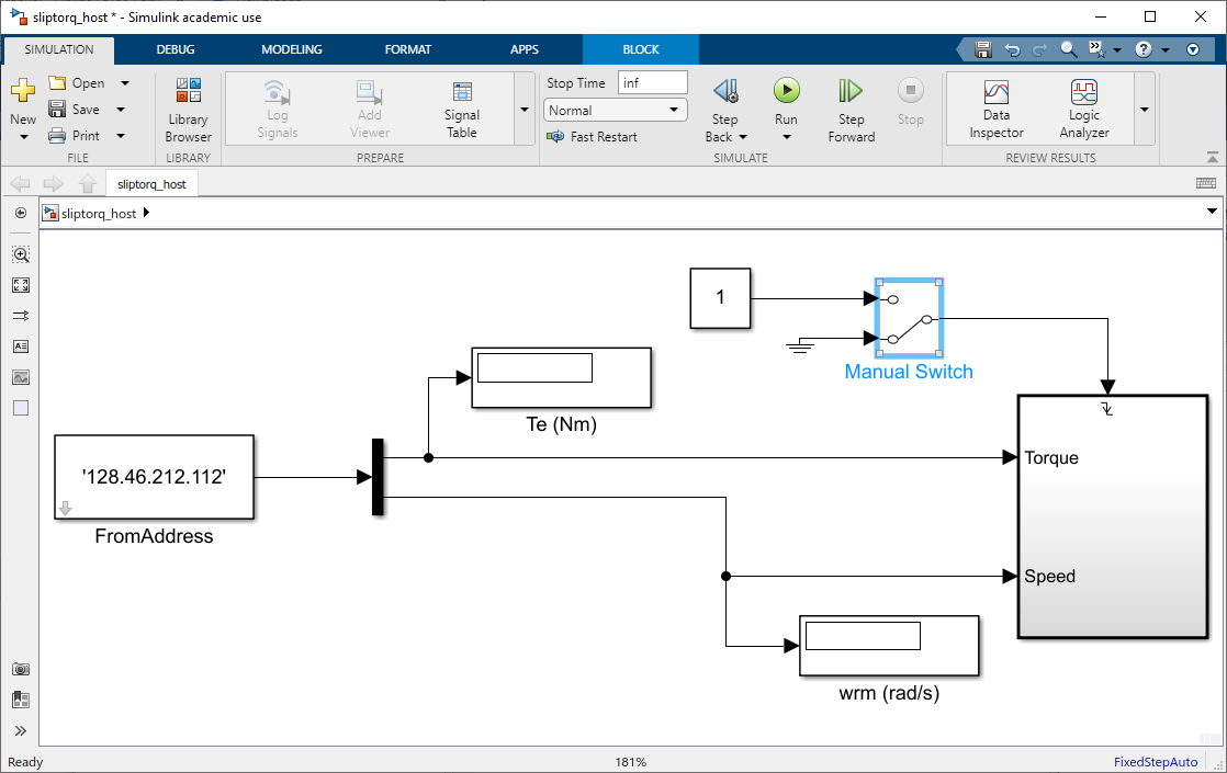
Fig. 14.3 Simulink host model for lab 14.#
Copy the file
lab_14_ts.matto your ECN account and email it to your partner in a zipped folder. You will need this file to complete the post lab.Plot the measured torque-versus-speed characteristics with those predicted in last week’s postlab on the same axis. Print the results.
14.3.2. Servo Operation#
Leave the induction motor connected to the torque transducer. Block the end of the torque transducer connected to the DC motor to prevent it from turning. Execute the program
slip_torque_target.slxand set the amplitude of the phase-\(a\) voltage to \(\qty{10}{\V}\), the amplitude of the phase-\(b\) voltage to \(0\), and unplug the DC motor from Channel 3. Record the steady-state torque usingslip_torque_host.slxby toggling the switch from \(1\) to \(0\).Increase the amplitude of the phase-\(b\) voltage to \(\qty{2}{\V}\), and record the average steady-state torque. Repeat the previous measurement in \(2\)-\(\V\) increments up to \(\qty{20}{\V}\), leaving the host model running for the duration of this test. Clear the workspace, then stop the host model upon completing all measurements, and save the torque data by typing
save lab_14_servo. Plot the average torque versus the amplitude of the phase-\(b\) voltage. The resulting plot should be linear.save lab_14_servo
The analysis for this mode of operation is given in Chapter 9 of the ECE 32100 text, which is not normally covered in ECE 32100. The purpose of this exercise is to demonstrate the operation of the induction motor as a servomotor wherein the amplitude of the control winding voltage is used to control the motor torque. This might be useful in position control systems.
14.3.3. Single-Phase Operation#
Ask your instructor to disconnect the torque transducer from the induction motor. Run the program
slip_torque_target.slx.Disconnect the phase-\(b\) winding from Analog Output Channel 2. This is not the same as setting the output of Analog Output Channel 2 to zero. Why?
Apply a \(20\)-\(\V\) sinusoidal voltage to phase \(a\). Does the rotor begin to turn? (It shouldn’t). With a twist of your finger, spin the rotor in one direction. Does the rotor continue to rotate? (It should).
With your fingers, apply a load torque to stop the rotor. With a twist of your fingers, twist the rotor in the opposite direction. Does it continue to rotate in the opposite direction? (It should).
This represents the single-phase mode of operation which is frequently used in home appliances. The analysis for this mode of operation is given in Chapter 9 of the ECE 32100 text which is normally covered in a more advanced class. In this mode, the phase current produces two equal-amplitude CW and CCW rotating magnetic fields as was demonstrated in Experiment 9 - Permanent Magnet Synchronous Motor (A). When you turn the motor in one direction, it attempts to follow one of the rotating fields. When you turn it in the other direction, it tries to follow the other rotating field. At stall, the tendency to rotate in one direction is canceled by an equal tendency to rotate in the other direction. Unfortunately, we can’t get into much more detail without covering Chapter 9.
14.4. Postlab#
Compare the analytical and measured torque-versus-speed characteristics that you plotted in Torque-Versus-Speed Characteristics (include your plot). Explain discrepancies.
For servo mode, plot the average stall torque versus the amplitude of the control-winding voltage. Can we make the amplitude of the control winding voltage negative? Will this result in a negative average torque? (Yes and Yes). Explain briefly.
In the single-phase mode of operation, how do the amplitudes of the forward and backward rotating magnetic fields compare to the amplitude of the rotating magnetic field for normal two-phase operation. (You may want to review the results of Permanent Magnet Synchronous Motor (A) before answering this question). How much torque can be produced during single-phase operation compared with normal two-phase operation? (An educated guess with a brief explanation will suffice).