6. Variable Reluctance Stepper Motor (B)#
Objective
In this experiment, the electromechanical characteristics of a variable-reluctance stepper motor will be investigated. The static torque-versus-position characteristics will be measured and compared with analytical predictions. We will also examine steady-state operation at constant step rates and experimentally establish the maximum start rate and maximum step rate.
6.1. Introduction#
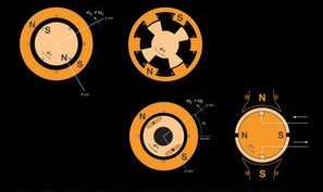
The voltage equations of a three-stack variable-reluctance stepper motor may be expressed
where
The self-inductances may be expressed in the form
where \(RT\) denotes the number of rotor teeth and \(SL\) is the step length. From (9.2-3) of the EE321 text,
Here, \(N = 3\) is the number of phases. The electromagnetic torque may be expressed
6.2. Prelab#
Carefully review the lab and postlab sections. Keep the postlab questions in mind when performing the experiments. Make sure you keep accurate notes in your lab notebook in order to be able to answer postlab questions.
6.3. In the Laboratory#
In the first part of the lab, we will measure the torque-versus-position characteristics of our stepper motor. The basic setup is the same as in last week’s lab (Figure 4b-1). The given motor is a 3-phase device with polarity markings defined as follows:
Phase |
Positive |
Negative |
|---|---|---|
\(a\) |
Black |
Yellow |
\(b\) |
Orange |
Blue |
\(c\) |
Red |
Green |
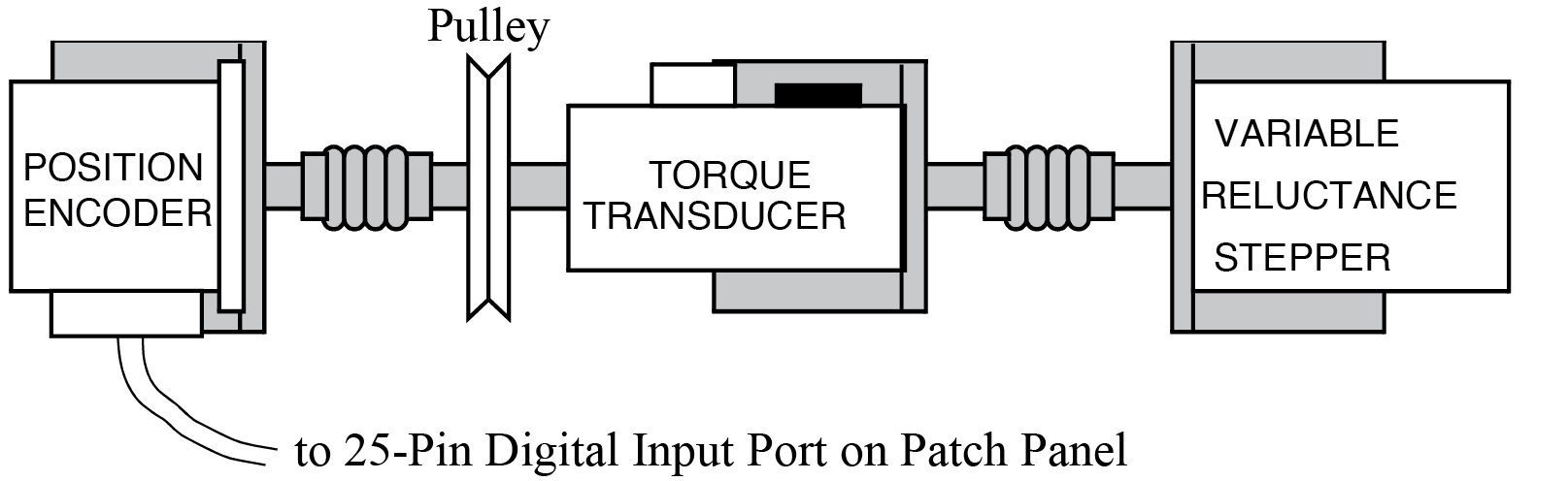
Fig. 6.1 Setup for lab Variable Reluctance Stepper Motor (B).#
6.3.1. Measuring Static Torque-Versus-Position Characteristics:#
The torque-versus-position will be measured using the pre-built Simulink models
T_vs_pos_tgt.slxandT_vs_pos_host.slx. The top-level views of these models are shown in Fig. 6.2 and Fig. 6.3, respectively. Connect the analog output of the torque transducer (red wire) to Analog Input 1. Set the range of Analog Input 1 to +1 V (middle position). The output of the position transducer should still be connected to the 25-pin Digital Input port.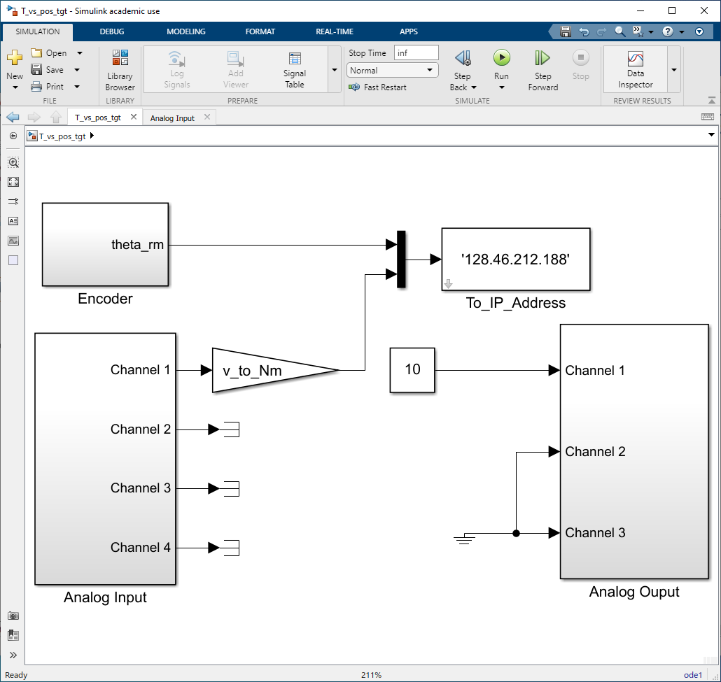
Fig. 6.2 Simulink target model
T_vs_pos_tgt.slxfor measuring torque versus position.#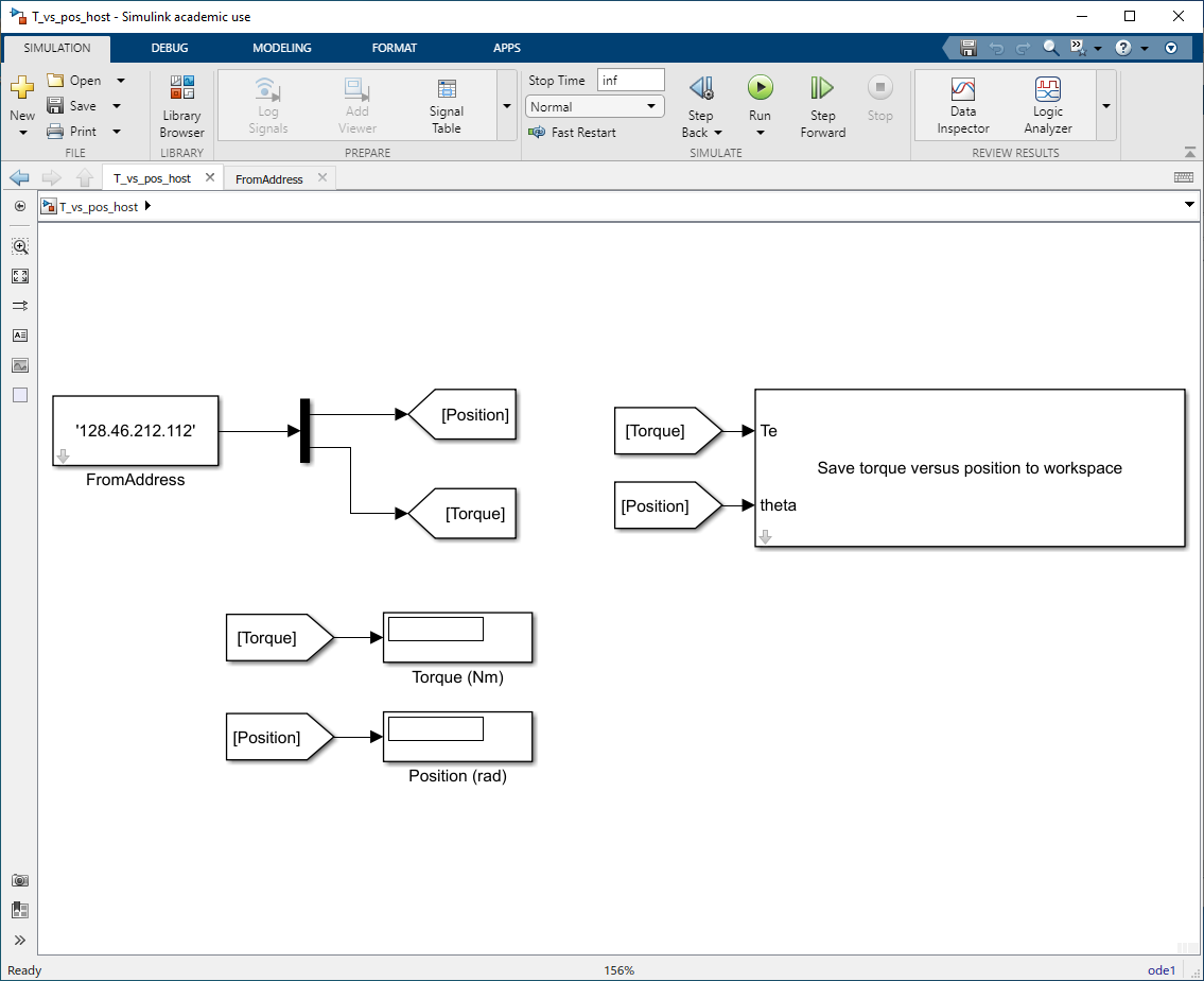
Fig. 6.3 Simulink host model
T_vs_pos_host.slxfor measuring torque versus position.#Open
T_vs_pos_tgt.slx. Build, connect to target, and run this model. Connect phase \(a\) to channel 1 of the patch panel. A successful build will be noted in the View Diagnostics window.The simulation that will run on the host computer is configured as a Normal simulation. This simulation samples the output of blocks in the target computer simulation,
T_vs_pos_tgt.slx. The position and torque of the stepper motor are displayed in digital displays of the model window.Zero out the torque transducer by pressing the “tare” button before running the host simulation. Allow the rotor to settle to its equilibrium position. In the model window of
T_vs_pos_host.slx, select Run to begin the host simulation. Record the position of the rotor from the numeric display. Using your hand, rotate the motor rotor slowly and as smoothly as possible from the encoder end of the torque transducer. As the rotor rotates, the computer calculates a new value of torque for each position the motor rotates through and updates the digital displays of the host simulation. After rotating the rotor through one complete revolution, stop the host simulation. Use the following Matlab command line to save the data:steptorq ('ta.mat', position, torque)
The resulting data file
ta.matcan be used for subsequent plotting and analysis using Matlab.Disconnect the patch panel output from phase \(a\) and connect it to phase \(b\). Restart the host simulation. Measure the torque versus position of the phase-\(b\) winding as done with the \(a\) winding. Again, save the data in file
tb.mat. Repeat the previous steps for the phase-\(c\) winding, saving the data intc.mat. Loadta.matinto MATLAB. The data will be stored as 2-column matrices of position (radians) and torque (N-m). Separate the data into vectors of torque and position.qrma = position torquea = torque
Repeat these MATLAB commands for phases \(b\) and \(c\) by loading
tb.matandtc.mat, substituting the appropriate letter for theainqrmaandtorquea. Plot the three torque curves.plot(qrma, torquea, qrmb, torqueb, qrmc, torquec)
Compare the plotted results with those predicted in the previous Postlab by plotting them on the same axis. Try to resolve gross discrepancies. Print the results and save your MATLAB workspace by typing save lab6_te. Copy the file
lab6_te.matto your ECN account and email it to your partner. You will need this file to complete the post lab.
6.3.2. Steady-state operation at a constant stepping rate#
Open the Simulink target model
full_step.slx, shown in Fig. 6.4. Excite the three stator phases with full-step square waves at a rate of \(10\) step/sec (phase-\(a\) winding is excited with a positive DC voltage, then phase \(b\), then phase \(c\), then phase \(a\), etc.) by setting the frequency of the signal generator to \(\qty{10}{\hertz}\) with an amplitude of \(1\). Start the target computer by connecting to target and pressing Run on Target. Clicking the manual switch should cause the motor to start rotating. Since this a three-phase motor, the frequency of each of the applied stator voltages (i.e. frequency of phase \(a\), \(b\), or \(c\)) is \(1/3\) the step rate. Based upon the known step length, what is the corresponding average rotor speed (in rad/sec) of the \(10\)-\(\hertz\) step rate?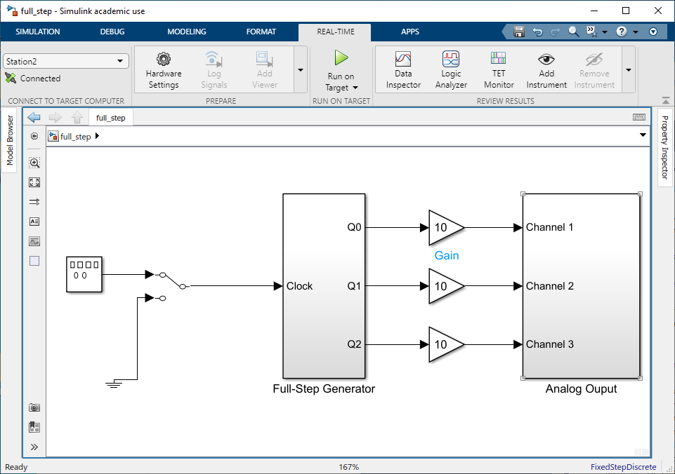
Fig. 6.4 Simulink model for operation at constant stepping rate,
full\_step.slx.#Using the digital oscilloscope and BenchVue, record and print the phase-\(a\) voltage, phase-\(b\) voltage, phase-\(a\) current, and phase-\(b\) current in the full stepping mode. Do you see any similarity to the current waveform and the current waveform for the solenoid pull-in measured in Electromagnetic Forces (A)? Be prepared to explain the similarities/differences in the postlab.
Apply a small load torque (pressing on the pulley with your finger) to the rotor, but not so large as to cause the motor to fall out of step. Note any differences between the loaded and unloaded current waveforms.
Which direction does the motor turn for the \(abc\) step sequence (CW or CCW with respect to the connected motor shaft)? What happens if one of the motor phase’s polarity is reversed (say phase-\(a\) polarity). What happens if two phases (say phases \(a\) and \(b\)) are swapped?
6.3.3. Maximum initial start rate:#
With the rotor initially at rest (\(0\) steps/sec), change the step rate to \(10\) steps/sec. Did the rotor fall out of step? If not, stop the rotor and repeat the step change of the step rate from \(0\) to \(20\) steps/sec. Repeat this experiment in increments of \(10\) steps/sec until you have established the maximum step rate that can be suddenly applied to the motor (i.e. how big a step in step rate) from rest. Note: when the motor does not rotate at the applied step rate, this is called “falling out of step”.
6.3.4. Maximum rotation rate:#
With the rotor initially at rest (\(0\) steps/sec), change the step rate to \(10\) steps/sec. Increase the rotor step rate (without stopping) in increments of \(10\) steps/sec until you have established the maximum step rate that the motor can sustain. How does this rate compare with the initial step rate measured in the previous section.
6.3.5. Modes of commutation:#
Stepper motors can be run in half-step and full-step modes. Full stepping is accomplished by driving the motor with only one phase energized at a time (\(a\)-\(b\)-\(c\)-\(a\)-…). Half stepping is accomplished by overlapping two phases (\(a\)-\(ab\)-\(b\)-\(bc\)-\(c\)-\(ca\)-\(a\)-…). By energizing two phases at a time, the stepper motor will effectively have twice as many steps due to the \(ab\), \(ac\), and \(bc\) half-steps between the \(a\), \(b\), and \(c\) full steps. The half-step mode will give the motor more step resolution and make the motor run smoother but requires more power due to each phase being driven longer.
Open the Simulink model
half_step.slx, shown in Fig. 6.5. Using the digital oscilloscope and BenchVue, record and print the phase \(a\) voltage, phase \(b\) voltage, phase \(a\) current, and phase \(b\) current in the half-stepping mode. What is the duty cycle of each phase for half stepping (i.e. what percent of time each phase on?). What is the duty cycle for full stepping?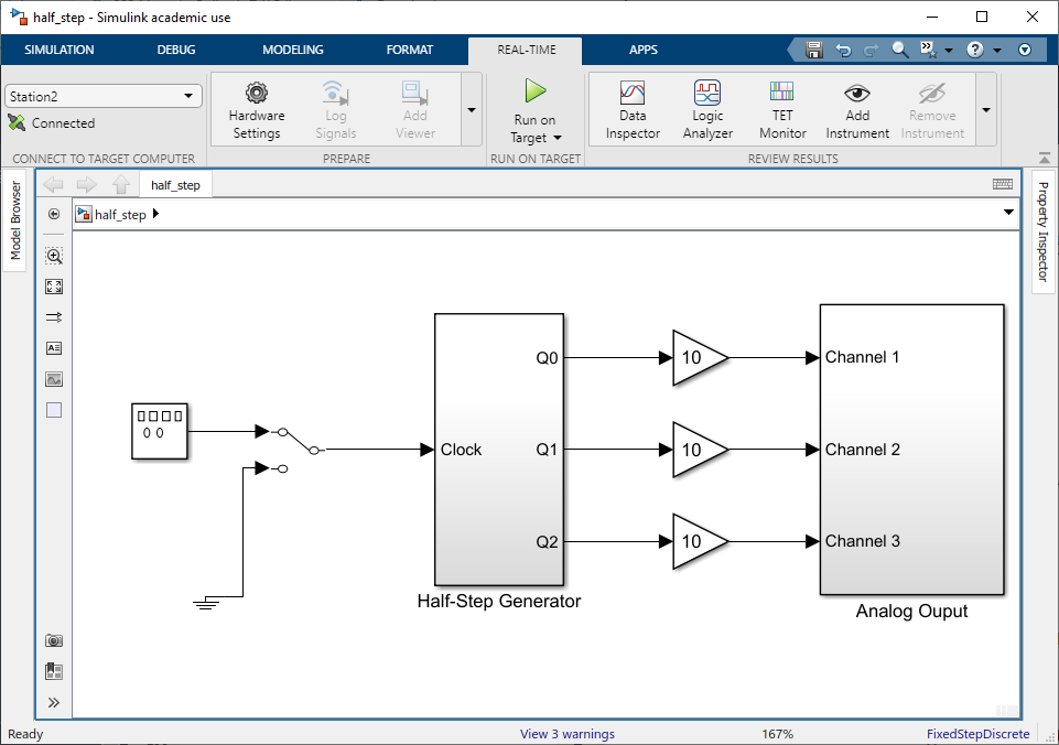
Fig. 6.5 Simulink target model for half-step operation,
half_step.slx.#
6.4. Postlab#
Compare the measured and predicted torque-versus-rotor-position characteristics. Specifically, superimpose the phase-\(a\) measured and predicted torque versus position on the same plot (make sure units are the same). Try to explain any discrepancies.
What is the difference between half stepping and full stepping? Consider the relationships between the phase \(a\), \(b\), and \(c\) voltages.
What happened when the polarity of phase \(a\) was reversed? Explain briefly? What happened when phases \(a\) and \(b\) were swapped? Explain briefly.
Discuss the shape of the phase-\(a\) current waveforms for half-step and full-step modes. Compare (qualitatively) with the results of Electromagnetic Forces (A).
What factors might influence the maximum start rate and maximum step rate (i.e. how might we increase the achievable step rate)?