9. Permanent Magnet Synchronous Motor (A)#
Objective
The purpose of this experiment is to demonstrate the development of rotating magnetic fields in ac devices.
9.1. Introduction#
In this experiment, the stator windings of a 3-phase permanent-magnet synchronous motor will be supplied by a balanced 3-phase variable-frequency voltage source and the rotor will be driven mechanically by the permanent-magnet DC machine used in Lab 8. The development of a rotating magnetic field will be illustrated using computer graphics, and computer simulation will be used to predict the electromagnetic torque of the permanent-magnet AC motor for various source frequency–rotor speed combinations. The dynamic performance will be measured and compared with simulated results.
9.2. Prelab#
Read or review Chapter 4 of text (up to Section 4.4).
9.3. In the Laboratory#
Our first objective will be to review the principles of rotating magnetic fields in 2-phase AC devices.
9.3.1. Development of Rotating Magnetic Fields#
Execute the program mmf from Matlab by typing mmf on the command
line. Select the HELP button to display the introduction on the
screen. For the electromechanical device considered in the program:
Determine \(\tilde{I}_{as}\) and \(\tilde{I}_{bs}\) so as to produce a counterclockwise (CCW) rotating magnetic field. Record these values in the lab notebook. Express the corresponding functions of time. Are these answers unique? Explain briefly.
Determine \(\tilde{I}_{as}\) and \(\tilde{I}_{bs}\) so as to produce a clockwise (CW) rotating magnetic field. Record these values in the lab notebook. Express the corresponding functions of time. Are these answers unique? Explain briefly.
Enter the values of \(\tilde{I}_{as}\) and \(\tilde{I}_{bs}\) selected above into the appropriate numerical fields of the dialog box. Note that the phasor magnitudes defined in mmf are the peak and not RMS magnitudes. By selecting various options that are available to you, address the following questions:
What kind of magnetic field does a stationary observer see?
What kind of magnetic field does an observer that rotates at in the CW direction see?
What kind of magnetic field does an observer that rotates at in the CCW direction see?
Use synonyms like: constant, pulsating (what is the frequency of pulsation?), stationary, rotating (what is the direction and speed?).
9.3.2. Magnetic Field Relative Strength#
Let \(\tilde{I}_{as}\) and \(\tilde{I}_{bs}\) be the phase currents in phasor form, and \(\tilde{I}_{+}\) and \(\tilde{I}_{-}\) be the components that produce clockwise and counterclockwise rotating fields. Now
or
Inverting, the forward and backward components can be expressed
Suppose \(\tilde{I}_{as} = 1 \phase{0}\) and \(\tilde{I}_{bs} = 0.5 \phase{90\degree}\). Determine the relative strength of the CW and CCW rotating components of the magnetic field using (9.4). Use Matlab to do the math. Repeat (3) for the given \(\tilde{I}_{as}\) and \(\tilde{I}_{bs}\). Note that when the source is unbalanced, the magnetic field may be decomposed into two components, each with different strengths.
Suppose \(\tilde{I}_{as} = 1\phase{0}\) and \(\tilde{I}_{bs} = 0\). Determine the relative strength of the CW and CCW rotating components of the magnetic field using (9.4). Repeat question 3 from Section 9.3.1 for the given \(\tilde{I}_{as}\) and \(\tilde{I}_{bs}\).
9.4. Postlab#
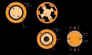
Our next objective will be to experimentally observe the development of rotating magnetic fields in the AC device shown in Fig. 9.1 where only one phase winding is shown for simplicity. This device is a 4-pole permanent-magnet synchronous machine (actually, its part of a brushless DC machine, but we won’t call it that until later). Here \(as_1 -as_1^\prime\) and \(as_2 -as_2^\prime\) represent sinusoidally distributed windings with \(\odot\) and \(\otimes\) indicating the locations where the turns density is maximum.
The \(as\) winding is comprised of the series connection of \(as_1 -as_1^\prime\) and \(as_2 -as_2^\prime\). Representative lines of magnetic flux for a positive current in the \(as\) winding are shown in Fig. 9.2. The actual flux distribution is distributed sinusoidally with peak densities occurring along the respective magnetic axes. Similarly, the \(bs\) winding, shown in Fig. 9.3, is comprised of the series connection of coils \(bs_1 -bs_1^\prime\) and \(bs_2 -bs_2^\prime\), and the \(cs\) winding, shown in Fig. 9.4, is comprised of the series connection of coils \(cs_1 -cs_1^\prime\) and \(cs_2 -cs_2^\prime\).
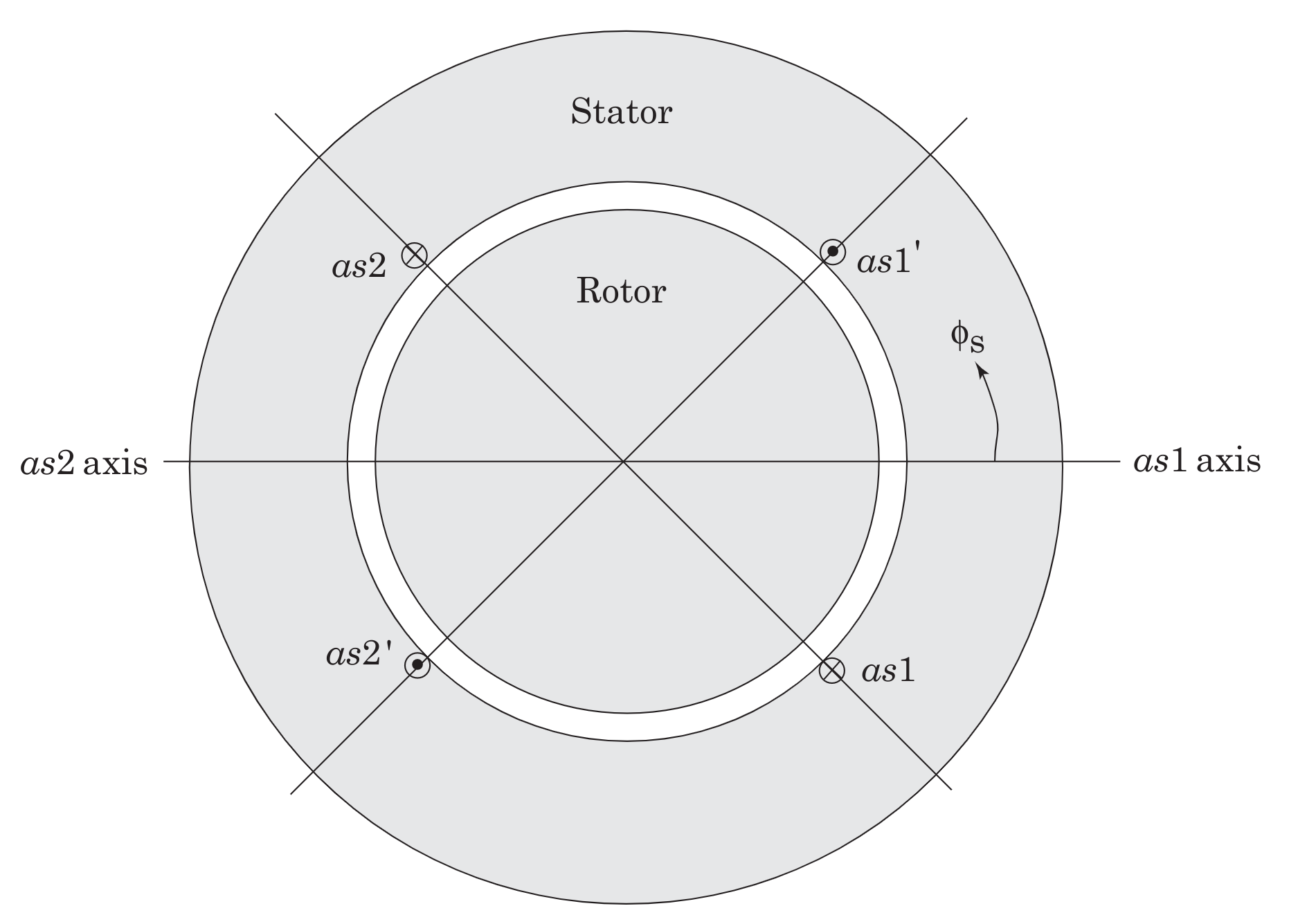
Fig. 9.1 Cross sectional view of 4-Pole single phase winding (phase \(a\)).#
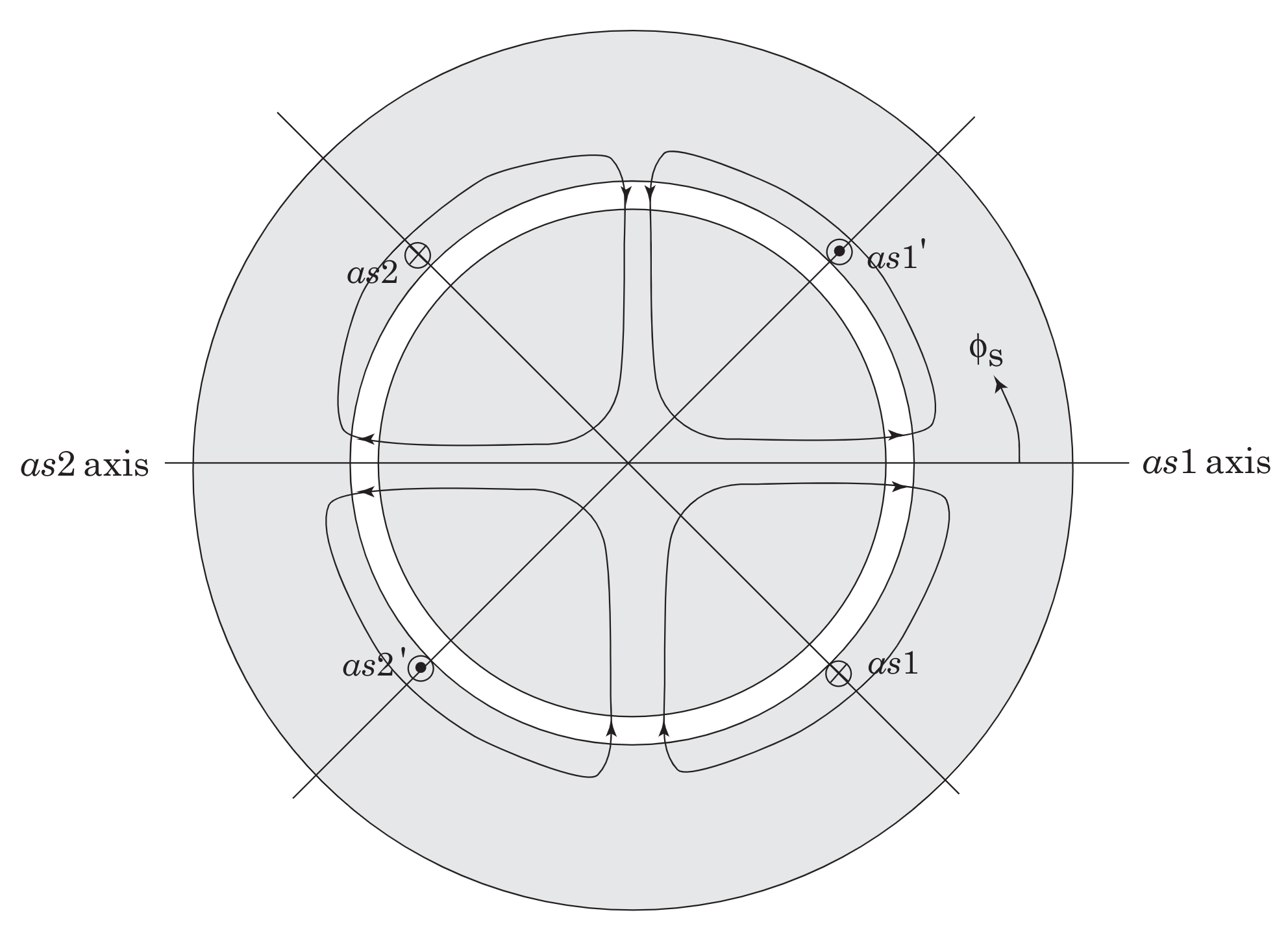
Fig. 9.2 Representative lines of flux for positive \(i_{as}\).#
Fig. 9.3 Winding configuration for phase \(b\).#
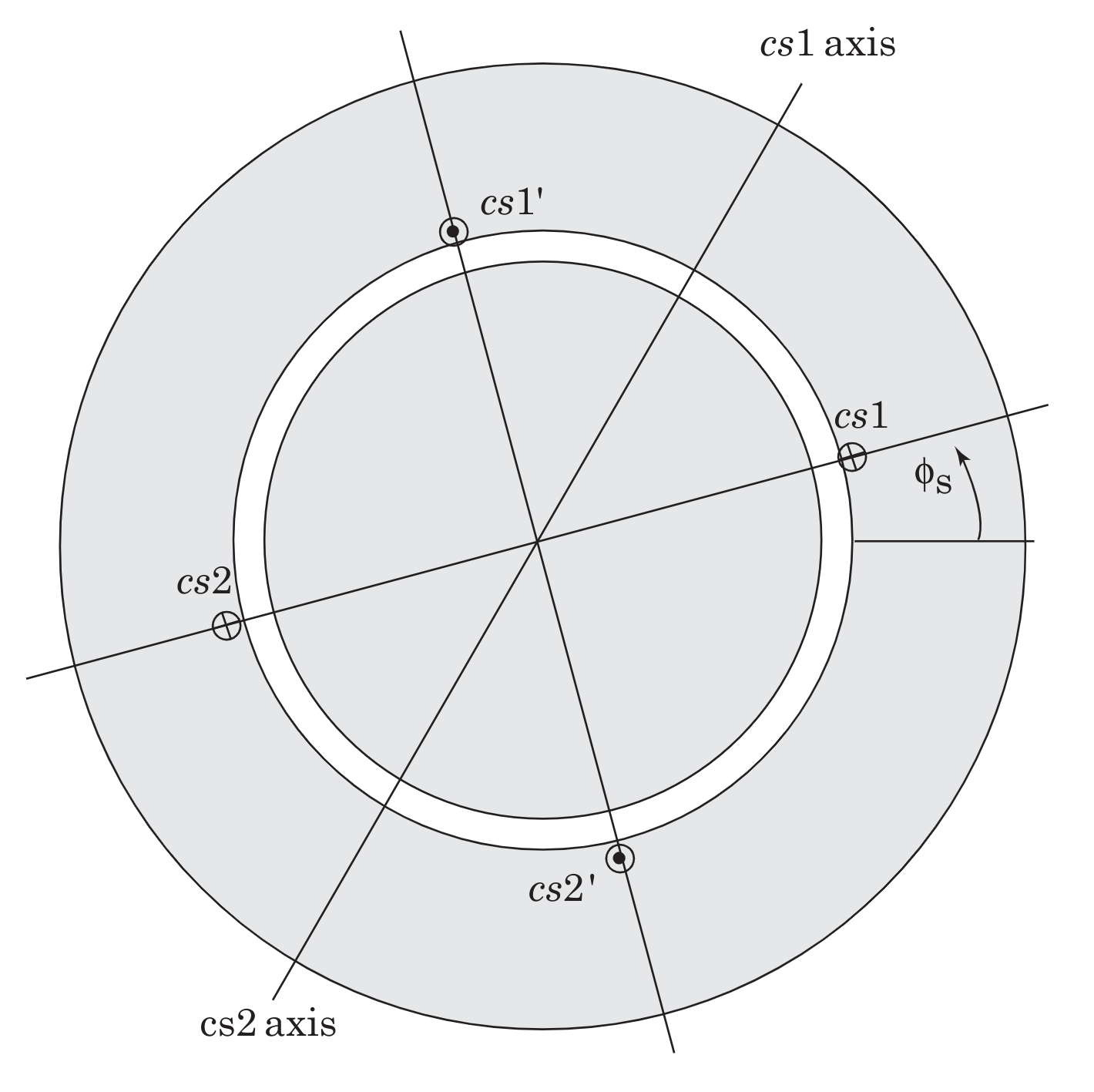
Fig. 9.4 Winding configuration for phase \(c\).#
Approximate the corresponding mmfs as sinusoidal functions of circumferential coordinate \(\phi_s\) (i.e. fill in the blanks):
(9.5)#\[\text{mmf}_{as} = K i_{as} \cos(\blank\phi_s + \blank)\](9.6)#\[\text{mmf}_{bs} = K i_{bs} \cos(\blank\phi_s + \blank)\](9.7)#\[\text{mmf}_{cs} = K i_{cs} \cos(\blank\phi_s + \blank)\]Suppose
\[i_{as} = 1 \cos \omega_e t\]\[i_{bs} = 1 \cos (\omega_e t-120^o)\]\[i_{cs} = 1 \cos ( \omega_e t +120^o)\]Show analytically that a rotating magnetic field will be produced.
In what direction will it rotate (CW or CCW)?
At what speed will it rotate (this is called the synchronous speed)?
At what speed must the rotor rotate in order to produce a non-zero average torque?
What kind of torque will be produced if the rotor rotates at a speed other than the speed of the rotating magnetic field?
What is the relationship between synchronous speed, the frequency of the applied currents, and the number of poles?