10. Permanent Magnet Synchronous Motor (B)#
Objective
The purpose of this experiment is to establish the fundamental electrical parameters of the permanent-magnet AC motor studied last week.
10.1. Prelab#
The electromechanical equations of a 3-phase \(P\)-pole permanent-magnet AC machine can be expressed in the form
where \(p\) is the differential operator \(\frac{d}{dt}\), and
Here, \(\lambda_{asm}\), \(\lambda_{bsm}\), and \(\lambda_{csm}\) represent the flux linkages of the stator \(as\), \(bs\), and \(cs\) windings, respectively, due to the permanent-magnet rotor while \(e_{as}\), \(e_{bs}\), and \(e_{cs}\) represent the corresponding induced voltages. Also,
where \(\theta_r\) represents the “electrical” position of the rotor whereas \(\theta_{rm}\) represents the actual mechanical position. If \(i_{as} = -i_{bs} -i_{cs}\), which is true due to Kirchhoff’s current law, show that (10.1) can be expressed as
Equivalently,
where \(L_{ss} = L_{ls} + \frac{3}{2} L_{ms}\). Similarly,
The electromagnetic torque may be expressed
In an ideal machine,
Substitute (10.13)-(10.15) into (10.12) and show that
Equations (10.9)-(10.11) and (10.16) define the electromechanical behavior of the given machine in phase variables. There are four basic parameters of the given machine: \(r_s\), \(L_{ss}\), \(\lambda_m^\prime\), and \(P\).
Next, suppose \(i_{as} = I_p \cos{\omega_e t}\), \(i_{bs} = I_p \cos{(\omega_e t - \frac{2\pi}{3})}\), and \(i_{cs} = I_p \cos{(\omega_e t + \frac{2\pi}{3})}\) where \(I_p\) is the peak current. Substitute these currents into (10.16) and show that
10.2. In the Laboratory#
10.2.1. Establish a Rotating Magnetic Field#
Our first objective will be to verify that a rotating magnetic field is produced in the given device. Connect the machine as shown in Fig. 10.1.
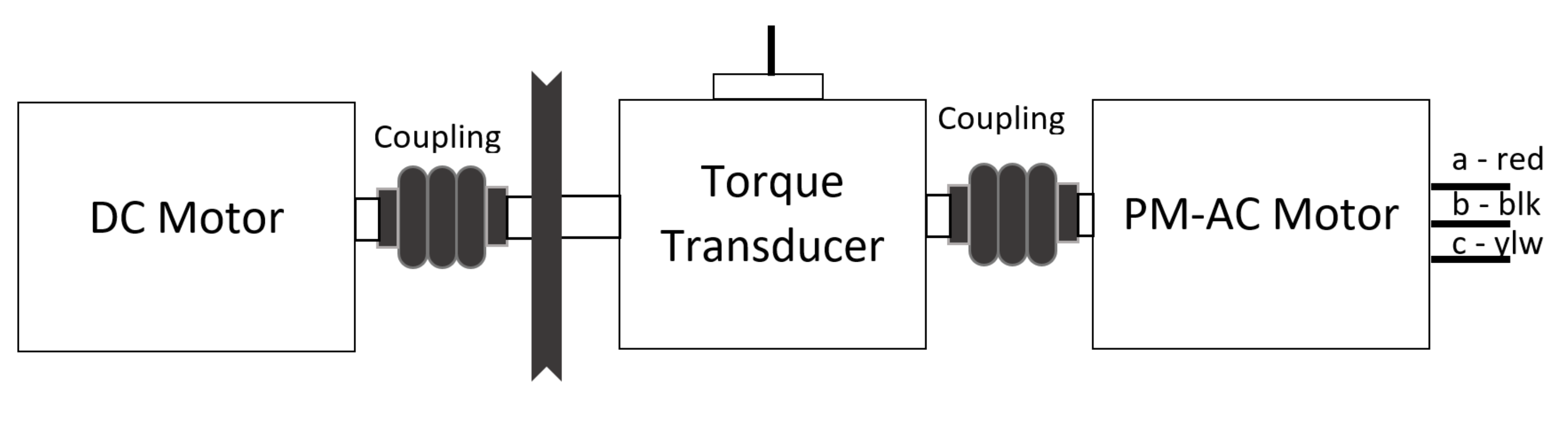
Fig. 10.1 Experimental setup for Permanent Magnet Synchronous Motor (B).#
Using
lab_10_target.slxFig. 10.2, apply balanced three-phase voltages to the three-phase windings. Set the frequency to \(\qty{5}{\hertz}\) and the amplitude to \(\qty{0.5}{\volt}\) peak. Make sure that the voltages are displaced from one another by \(\qty{120}{\degree}\). Record the applied voltages \(v_{ag}\), \(v_{bg}\), and \(v_{cg}\) including their amplitude, frequency, and phase delay.Caution
Never apply more than \(\qty{2}{\volt}\) to the motor or irreparable damage may result. When the motor is not being used, be sure to unplug the motor from the patch panel.
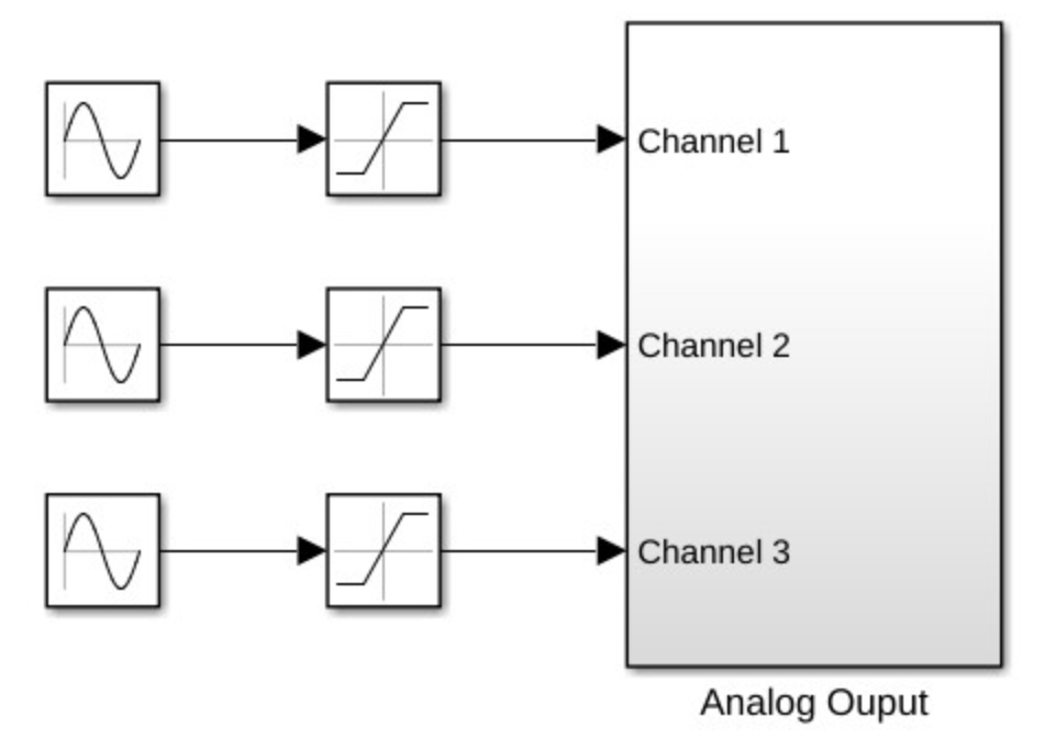
Fig. 10.2 Target model for Permanent Magnet Synchronous Motor (B).#
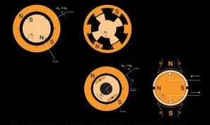
Record the direction of rotation (CW or CCW) as viewed from the right end of the AC motor. Approximate the speed of the rotor as follows. While your partner looks at their watch, count the number of revolutions of the pulley in a 1-minute period. Convert revolutions per minute to radians per second. How does this speed relate to the frequency of the applied voltages? How many poles does this machine have?
Interchange the \(b\) and \(c\) leads to the voltage source. What happens to the direction of rotation? Explain why this happens.
Next, hold the pulley to lock the position of the rotor. Measure the phase \(a\) current and shaft torque, displaying both signals on the oscilloscope. What is the frequency of torque pulsation? How does this frequency relate to the frequency of the applied voltages? Explain briefly.
Record the peak-to-peak current and the peak-to-peak output voltage of the torque transducer (you may use the horizontal cursors to establish this value). What is the corresponding peak torque in \(\newtonmeter\)? From (10.17), this peak torque is equal to \(\frac{3}{2}\frac{P}{2} \lambda_m^\prime I_p\) where \(I_p\) is the peak current (\(I_p = I_{\rm pk-pk}/2\)). Calculate \(\lambda_m^\prime\). Using BenchVue, print the data captured on the oscilloscope.
10.2.2. Measure Electrical Parameters#
Our next objective will be to measure the electrical parameters: \(r_s\), \(L_{ss}\), and \(\lambda_m^\prime\).
Stator resistance#
Apply balanced voltages to the three phase windings. Set the frequency to \(\qty{1}{\hertz}\) and the amplitude to \(\qty{0.5}{\volt}\) peak. Make sure that the voltages are displaced from one another by \(\qty{120}{\degree}\). Block the rotor to prevent it from turning. Measure the phase-\(a\)-to-ground voltage and the current into phase \(a\) using the oscilloscope. Verify that the voltage and current are essentially in-phase at this frequency. Divide the peak voltage by the peak current. This is \(r_s\).
Stator inductance#
Increase the frequency of the applied voltages to \(\qty{100}{\hertz}\). Calculate the impedance magnitude by dividing the peak voltage by the peak current. Calculate the inductance at this frequency. This is \(L_{ss}\).
Move the rotor to several different but fixed positions. Compare peak \(I_{as}\) at each fixed position. Record your observations. Based upon your observations, does the inductance vary with rotor position?
Flux constant#
Apply \(\qty{3}{\volt}\) to the armature of the DC motor, causing both motors to rotate.
Measure the phase \(a\) to phase \(b\) open-circuit voltages of the AC motor.
Measure the electrical frequency \(\omega_e\) of \(e_{ab}\) and calculate \(\lambda_m^\prime\). From the equations given at the beginning of this lab, show that the peak value of \(e_{ab}\) is equal to \(\sqrt{3}\omega_r \lambda_m^\prime\). Use this information to calculate \(\lambda_m^\prime\).
10.3. Postlab#
Compare the values of \(\lambda_m^\prime\) established using the two methods in this lab. Which do you think is more accurate? Why?
What is the relationship between the mechanical rotor speed and the frequency of the open-circuit voltages?
If the stator windings are short-circuited and the rotor is mechanically rotated at a speed of \(\omega_{rm}\), based upon the parameters established in this lab, what will be the peak amplitude of the resulting stator currents.
Hint
Consider (10.8).